
Hydraulic Flow
CPP pipes are made of High Density Polyethylene (HDPE) plastic raw material, which has a non-wetable, glass-smooth surface that makes it possible to use a Manning Coefficient of Flow Value of n=0.009 as shown on the graph below.
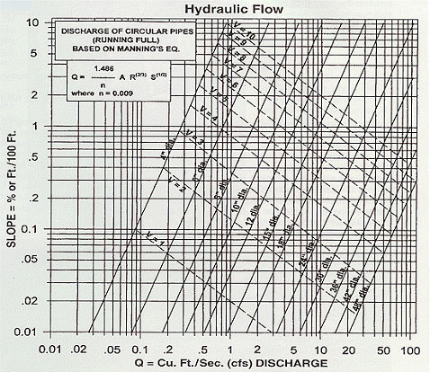
The Graph values for Velocity in feet per second (V), and for Flow Discharge in Cubic Feet Per Second (Q) are based on the HDPE raw material Roughness Factor (n) of 0.009. Because the pipe manufacturing process of temperature and melt flow may or may not effect pipe surface roughness, CPP selects n=0.010 as its base n factor for laboratory preconstruction pipe hydraulic flow estimates on CPP Smooth Core. CPP Single Wall n values will vary according to pipe size, and are shown on the Chart following. The installed n values for 12” and larger may vary from 0.011 – 0.014 depending on expected sediment loading and installation expertise. If it is desired to convert the Graph values to other n values as shown on the Chart below, one should divide the Graph values as follows:
0.010/0.009 = 1.111

1.111 for n of 0.010
1.444 for n of 0.013
1.555 for n of 0.014
1.666 for n of 0.015
1.888 for n of 0.017
2.000 for n of 0.018
2.222 for n of 0.020
|
Flow Restriction “n” Value Chart
|
||||
|
Diameter
|
CPP’S
Single Wall |
Galvanized
Corrugated |
CPP’S
Smooth Core/n-10 |
Concrete
|
|
4” |
0.014 |
N/A |
0.010 |
N/A |
|
To convert graph discharge of Cu. Ft./Sec. to Gal./Min. multiply by 448.8. |
||||
The Inert, Anti-Adhesive nature of HDPE also assists CPP pipes in their excellent hydraulics because it prevents the Scale-Slime-Sediment buildup that is common to pipes made of other materials. Pipe flow discharge rates for any gravity flow pipe system is determined by the Manning’s Flow equation. The “n” value in this equation for Roughness Coefficient is shown in the chart above.
Manning’s Equation
Q = (1.486/n) AR (2/3) S (1/2)
Where:
- Q = Flow (cfs)
- n = Manning’s “n”, a term used to describe material roughness (unitless)
- A = Cross sectional flow area of the pipe (ft²)
- R = Hydraulic radius (ft): ¼ the diameter for full-flowing circular pipes
- S = Pipe slope (feet/foot)
In using any pre-construction estimates concerning pipe hydraulics, one must keep in mind that preconstruction flow estimates depend greatly on the “state-of-the-art” knowledge of the installer, how level he positions pipes, manholes or applies couplers, etc. In addition, the amount and type of sediment expected in the fluid flow ca alter installed n-calculations. In gravity-flow pipe systems there are many things that are encountered in the field that can revise a laboratory environment water flow calculation. The preplanning stage as well as the construction stage of a project should take into account all the possible variables.
Hydraulic Flow
While some of the more tightly controlled manufactured concrete pipes may show an initial roughness coefficient that is equal to an HDPE pipe when first installed, the durability of HDPE over time will cause its roughness coefficient not to vary or increase with wear since the chemically inert HDPE is less effected by pitting and corrosion. This in turn will reduce maintenance and replacement costs over the years. Because the “n” factor will remain more constant over than the “n” factor of competing pipe raw materials, Downsizing with CPP’S Smooth Core n-10 on flat grades can be possible. Using smaller size CPP pipes at steeper grades to achieve higher flow rates is also possible because HDPE raw material based pipes are more abrasion resistant than competing raw material based pipes.
French and Farm Landscape Subsurface Drain
Hydraulic Notes
In gravity flow drainpipe systems the grade of the pipe greatly determines the water flow velocity as the included Hydraulics Graph and Chart indicate. Another important hydraulic factor to consider is the opportunity that water may or may not have for entering into a pipe system.
Inlet Drains and Catch Basins are structure devices for improving the opportunity of water to enter a pipe from above ground. In slow-soak, leach filtering subsurface gravity drain pipes, the rate of water entry is to a small degree determined by the Inlet Area sizing of perforations (slots or round holes) in the pipe.
The most important water inlet control factor for subsurface drain pipes however is the Percolation Rate (PERC Rate) at which water filters, oozes or trickles through a particular soil type profile. Water will not filter or perc through a heavy, stiff clay soil as fast as it will through a sandy or gravel soil type.
Local Farm Officers or Soil Conservation Service Engineers can supply general soil perc rates. At sites with several different soil types, soil perc rates can be complex to discern and even unknowable. To speed up a soil’s perc rate in a stiff or complex soil, rock or sand is often placed around the perforated underdrain pipe. This technique is also used in house basement perimeter subsurface drains.
A filter between the rock and the native site soil will prevent the native site soils from migrating with a subsurface water flow into the rock, and thus over time plugging up the rock rendering the rock-pipe system useless. If sand is used as a perc rate enhancer, a filter is generally applied directly to the pipe to prevent sand fines from entering the pipe.
These underground rock or sand pipe systems are sometimes called “French Drains”, and do not require the maintenance of trash removal from metal grates that a Catch Basin inlet system does. However, in very slow perc rate soils, some type of ground level, surface flow Catch Basin or Inlet Flow Drain structure may be required for improving the opportunity of water to enter a pipe system. Any good drainage system of any size will generally require a balance of both surface and subsurface drainage capability in order to handle both flash-flood rain events, and also long term soaking rain events.
For information on our perforated pipes water inlet areas click here