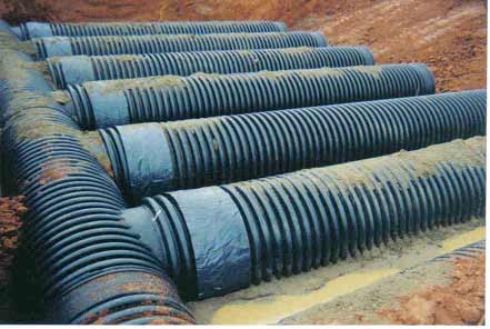
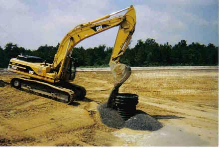
Installation
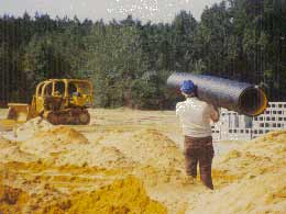
Eliminates Heavy, Expensive Equipment
And Saves Labor Time
Labor is always the largest cost component in any
buried pipe system.
|
CPP HDPE Culverts Drive Down Bid Prices
|
||||||||||||||||||||||||||||||
|
||||||||||||||||||||||||||||||
ODOT Pipe Analysis ShowsCompetition is Good A 1995 Ohio Department of Transportation study analyzed 22 projects; 50% limited to concrete, 50% allowing concrete and alternate materials. The study found a 22% cost savings when alternate materials were allowed. |
||||||||||||||||||||||||||||||
Plastic Pipe Will Drain Your Water,
Not Your Bank Account!
Call Us
1-910-525-4046 or Toll Free 1-800-334-5071
A Complete Design Manual for Corrugate Plastic Drainage Pipe is Available if you visit the PPI’S Web Site by clicking here:
Prevent Cave-Ins
Before beginning installation, one should note that OSHA Files show that trench Cave-Ins kill more construction workers per year than any other type of construction accident. This includes any type of pipe installation, cable installation or repair.
In any trench below ground water or below five feet deep, there exists a definite danger of sidewall collapse. Factors such as rainfall, water seepage and the weight plus vibration of nearby heavy equipment can all contribute to Cave-Ins. All OSHA regulations must be followed as with any pipe raw material conduit.
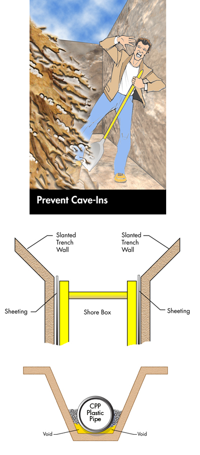
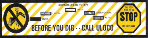
Be Careful When Installing Any Buried Pipe System
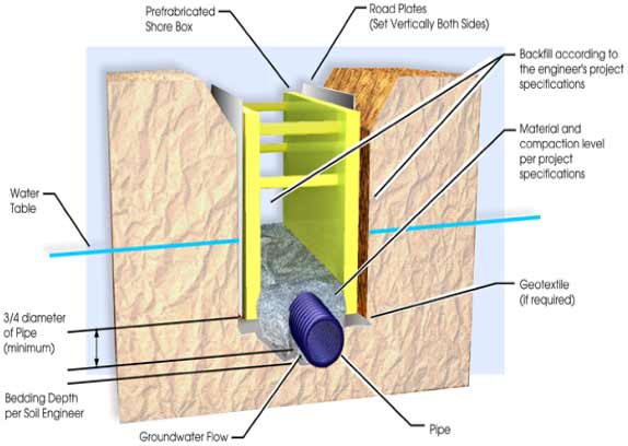
When trenching at unstable soil sites where a Safety-Shore Box could not offer protection, the trench walls should be slanted on a slope to prevent Cave-Ins. If trench wall support sheeting is required, and is driven into or below the pipe zone to prevent the loss of support foundation materials, Do Not remove unless directed by a soils engineer.
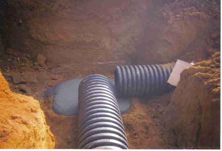
Trench detail shows placement of the non-woven filter fabric. Ground water is free to flow but the fabric stops movement of cohesionless soil. As with concrete, clay or metal pipes, do not disturb installed CPP pipe and its filter wrapped embedment zone when moving the Safety-Shore Box to the next pipe joint installation position.
A Complete Design Manual for Corrugate Plastic Drainage Pipe is Available if you visit the PPI’S Web Site by clicking here:
Installation Cover Sequence
|
Maximum Cover Height Table In Feet Backfill Condition |
|||||||||
|
Class I |
Class II
|
Class III |
|||||||
|
Pipe Dia.
|
Uncompacted
|
Compacted
|
85% | 90% | 95% | 100% | 85% | 90% | 95% |
|
4” |
17(ft)* |
59(ft) |
17(ft) |
24(ft) |
37(ft) |
59(ft) |
15(ft) |
18(ft) |
24(ft) |
NOTE: All Depths of Twenty (20) feet or more require The Design Engineering input of a Geotechnical Civil Engineer. Special Applications such as Dams, Landfills also require additional Civil Engineering input.
|
Table 1
|
||||
|
Soil Classification
|
||||
|
Class I
|
Class II
|
Class III
|
Class IV
|
Class V
|
|
Stone ¼” to 1 ½” diameter. Crushed gravel, stone, slag, shells, marl.
|
Coarse Sand or crushed stones or gravel of 1 ½” maximum particle size.
|
Clayey gravel, fine sands; also sand-clays and gravel clay mixtures. |
Silts, inorganic clays or silts of high plasticity and liquid limits. Not recommended for bedding, haunching or initial backfill. Requires a Geotechnical Engineer’s evaluation prior to use.
|
Organic soils, frozen soils, rock over 1 ½” and other foreign debris like roots, construction trash, etc.. Requires a Geotechnical Engineer’s evaluation prior to use.
|
The above chart only gives a general overview of each soil type. For actual engineering design work, the expanded description necessary for understanding the obtainment of a satisfactory pipe embedment stiffness can be seen in ASTM-D-2321 on Tables 1 & 2.
Table 2 gives the Minimum Soil Cover requirements for 3” to 48” diameter pipe as a function of H-Truck Live Loading. The cover depths shown have been tabulated for two soil conditions: (1) Fair, which represents a Class III soil compacted to 85% proctor density; and (2) Good, which represents a Class III soil compacted to 95%. The accompanying CANDE graph shows pipe deflection decreasing as compaction or depth increase, and the maximum Cover Height Table is shown above.
|
Table 2
|
|
|
Minimum Cover Height |
|
|
Inside Diameter, |
Minimum Cover |
|
3 (75) |
1 (0.3) |
Minimum Cover Height Table 2 and CANDE graph source: The Corrugated Polyethylene Pipe Association Study titled “Minimum Cover Height for HDPE Corrugated Plastic Pipe Under Vehicular Loading” by Katona – 1988
Installation
Trenching & Bedding Sequence
Trenching Installation Sequence
An undisturbed, firm trench wall is the unmovable base against which the compacted Soil Envelope material that immediately surrounds the pipe rests. The undisturbed, firm trench wall and the Compacted Envelope together actually carry the load. In stable soils excavate as narrow a trench as needed to install, and compact around the pipe. Narrow trenches will save time and compaction costs. If trenching in unstable soils, a trench of 1.5 times the pipe diameter plus twelve inches is the minimum width required. A soils engineer however may require additional excavation in order to stabilize or bridge over soft soil pockets. Also when trenching in unstable soil, the trench walls should be slanted on a slope both for safety, and to assist the installer in preventing the pipe from being misaligned by unstable soil cave-ins. As noted in Table 1, Class IV and V soils require the evaluation of a Geotechnical Engineer. Gravel packed envelopes enclosed in a filter wrap are generally required per ASTM-D-2321 to provide pipe support, and control water migration of cohesionless material. ASTM-D-2321 also notes other soil stabilization option strategies in addition to gravel packed filter wrapped pipe support cells.
Bedding Installation Sequence
Just as firm trench walls provide solid side support and prevent side shifting in plastic pipe systems, so too must the bed upon which the pipe lays be free of soft spots to provide longitudinal support along the length of the pipe. If the pipe is not uniformly supported along its length by a firm, unmovable floor or bedding, then differential settlements can cause pipe sagging to occur. Sagging can create water flow backups. To provide good longitudinal bed support, construct the Bedding Zone per the appropriate Soil Type as described in Table 3. The Bedding Zone as shown in the Pipe Cover Sequence Diagram is the top of the trench grade that the pipe lays on. This Bed should be Smooth and Free of Large Rocks or other protrusions, which may cause point loading on the pipe. Do not allow rocks of over 1 ½” to come in contact with the pipe. Class I soils are smooth graded. Class II and III soils are smooth graded, and then compacted to desired grade. Class IV and V soils must be over excavated by at least 6 inches and filled with compacted material to grade per Table 3. A geotechnical evaluation may require additional over excavation and filter wrapped fill if a future high water table level is expected in the pipe support zone.
|
Table 3
|
|||
|
Trench & Bedding Construction Methods Per Soil Classification
|
|||
|
Class I
|
Class II & III
|
Class IV
|
Class V
|
|
Excavate to grade and begin installation. Make sure no rock over 1 ½” in size makes contact with the pipe.
|
Excavate to a point above grade & compact loose material to the desired Bedding Compaction Density Percentage.*
|
Since this soil is not readily compactable, excavate at least 6” below grade. Then fill & compact a Bedding Layer to grade. ** A geotechnical evaluation is required. |
Similar to Class IV. However, may need to excavate over 6” to below existing groundwater or future predicted grade water level. **A geotechnical evaluation is required.
|
The above chart only gives a general overview of each soil type. For actual engineering design work, the expanded description necessary for understanding the obtainment of a satisfactory pipe embedment stiffness can be seen in ASTM-D-2321 on Tables 1 & 2.
* NOTE: If using a Class I Stone envelope material in a trench of Class II soil, use a filter wrap. If using a Class II sand envelope material in a trench of Class III soil, use a filter wrap.
**NOTE: Must use a filter wrap or employ other soil stabilization strategies in Class IV or V soils as noted in ASTM-D-2321 per the determination of a geotechnical engineer.
Pipe Cover Sequence
If a Class I stone material is used for Bedding material in a Class II or lower soil type classification trench, a Filter Wrap should be placed down prior to adding the Bedding material. A Filter Wrap, as shown in Filter Diagrams A & B, will allow water to pass, but prevent the trench Bed or Wall soils from migrating with rain waters into the rock envelope. This will stabilize both the Envelope Zone and the Support Soils that surround it. If a Class II soil is used for Bedding material in a Class III or lower soil type trench classification a Filter Wrap should be used also. In addition to a filter wrap, an Anti-Seep Collar maybe required along the pipe run to prevent the water flow migration of soil fines along the length of the pipe.
Lay down filter fabric prior to placing loadbearing envelope material and foundation bedding materials.
Water can pass easily through the gravel-pack or a sand envelope’s exterior filter wrap, while waterborne fines are filtered out. This construction technique will provide both a stable envelope soil and a stable trench soil.
Haunching Backfill Sequence
The Haunching Zone as shown in the pipe cover sequence diagram is between the Bedding Zone and the Lower Half of the pipe below the Spring Line. If a Class I type of rock or stone was used in the Bedding Sequence, it is mandatory that it be used in the Haunching Backfill Sequence up to the Spring Line. This continued use of Class I material will prevent the loss of Haunching’s side support that would occur if a Class II or Class III soil were used since these latter soil types would migrate into the voids of a Class I stone type bedding base. If a Class II sand was used in the Bedding Sequence of a Class III soil, the Class II should be used up to the Spring Line for haunching backfill material also as different soils in the haunching area may react differently to moisture changes.
The continued use of the same material from Bedding to Spring Line in conjunction with the use of a filter fabric will stabilize the environment in which the pipe is buried. If the pipe is being installed below existing or future predicted groundwater levels, a Class I must be used to the Top of the pipe encased in a filter wrap. CPP Water Tight or Mastic Wrap leak resistant couplers as described in the coupler section must be used at expected high water sites to prevent the water migration of cohesionless soils into pipe joints that could cause future sinkholes.
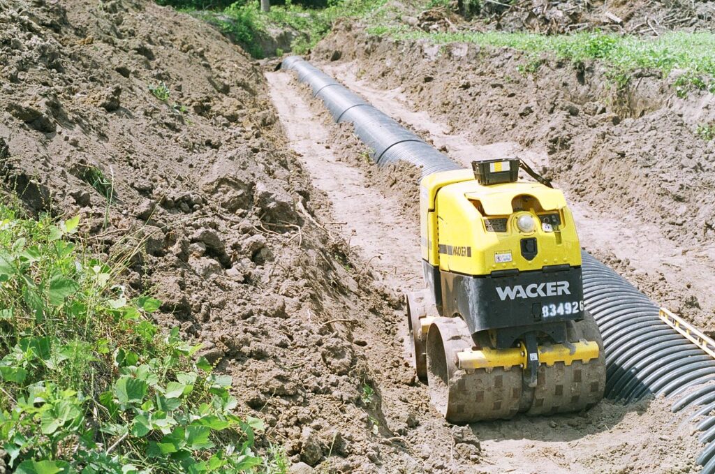
If a Class I stone is used as Haunching Envelope material, simple dumping and leveling can achieve the required compaction level. If a Class II sand is used, employing the water spray compaction method to obtain the required compaction density is effective. Layout the sand in 6 inch lifts and spray each lift, but avoid saturation and puddling. As a rule of thumb, the dryer the soil, the stronger and more stable it is. However, a slightly damp material will generally result in maximum compaction with minimum effort. Do not use this method in freezing weather though, as ice pocket voids maybe created.
While Class III soils are allowed as a compaction envelope material, more care and compaction time must be taken to achieve the required proctor density compaction level. Class III soils should be laid out in 3 inch lifts. Even though water-spray compaction is allowed in Class III soils, Hand-Held tamping is generally recommended because this can be faster than waiting for the sun and air to dry out each lift. As a result of the extra time spent on compaction, Class III soils can be more expensive to use than imported Class I or Class II soils even if the Class III soil is provided free.
Many knowledgeable pipe contractors economize both labor cost and imported soil envelope cost at Class III sites by importing a Class II sand, and mixing this 50/50 with the site native Class III soil. The native Class III soil generally provides enough dampness when mixed with the Class II sand to provide a quick maximum compaction job with little effort. The final compacted soil’s moisture content should be 9.5% or less. If a higher post-construction, soil moisture content is expected, a filter wrapped soil support cell should be considered.
To make sure that no movement occurs in the pipe during Haunching, Special Care should be taken to adequately fill and shape the Haunching material to the Bottom Half Curvature of the pipe equally all on each side. Failure to adequately fill and compact under the Spring Line bottom half Curvature can create loose voids that will later allow movement during a live load. To avoid this, place the Haunching fill material in 3-inch or 6-inch layers, and compact prior to laying down another lift. If using the water spray compaction method, do not puddle, and allow each layer to solidify. Be sure to compact each layer out to the undisturbed trench side wall for assured side wall lateral support.
Equal compaction on each side in layers will prevent pipe from shifting during the construction phase. By extending the compaction fully to the firm and undisturbed sidewall, the lateral stiffness needed to prevent pipe side – shifting under traffic loads is assured.
Initial Backfill Sequence
This sequence covers the space between the pipe’s Springline to a point 6” above the top of the pipe; it takes place in two steps: (1) Step one is from the Springline to the Top of the pipe. (2) Step two is from the top of the pipe to a point 6” above the Top of the pipe. Place each lift, and compact to the required standard proctor density. If using the water spray compaction method, allow time for each damp layer to solidify until it will support the weight of a man before adding the next lift. In compacting this initial backfill sequence, do not use heavy mechanical compaction equipment directly above the top of the pipe until ample backfill has been added to prevent the compaction event from causing the pipe to deflect or bend out-of-round. Light hand tamping or water spray compaction, which will solidify soil and eliminate voids without deflecting the pipe, is recommended here for Class II or Class III soils; Class I soils will compact upon dumping with little extra effort other than smooth grading. In this compaction phase, compact the sidewall portion of the backfill fully to the sidewall, as sidewall lateral support is what is essential for the load carrying. Again, only use light hand tamping or water spray to compact away loose material over the top. Provide at least 48 inches of cover Directly Over The Top before the utilization of a hydrohammer for compaction. If using a front-end loader to deposit Class I or Class II material in the trench, Featherdump in 6” layers so the required compaction can be achieved quickly. If using a Class III material, dump in 3” layers. Once step two has been completed 6” above the top of the pipe in this phase, close off the filter fabric wrap by overlapping if filter has been required.
6” Bedding Zone Required Under Pipe
Water spray compaction is effective, and labor cost efficient in Class II sand soil types. Class III soils however can be compacted over a wide range of densities due to moisture variability potential. To achieve good compaction in Class III soils, the soil’s moisture content should be 9.5% or less. In these soils, compaction installation economies can be achieved by mixing imported sand 50/50 with the native Class III clays.
Final Backfill Sequence
When the Initial Backfill Sequence has been installed to a point 6” above the top of the pipe, and the filter has been overlapped to the closed position, only an additional 6” of Compacted material is needed in this, the Final Backfill Sequence, if Live Load Traffic Bearing is expected. Otherwise, Compacted Class I, II or III material is not needed in the Final Backfill zone except as specified by an engineer in a Class IV or V soil or high water table situation. Also at depths of more than 20 feet deep, additional compacted material maybe needed in the Final Backfill zone depending on the soil type profile at each site as determined by an engineer.
Class I Rock & Marl cover provides H-20 live loadbearing service with 12” of cover. H-20 loadbearing includes cars, vans and tractor-trailers as shown elsewhere in this booklet.
Paving
As a footnote to Trench and Cover installation requirements, the paving material of concrete and asphalt should be noted. In most construction cycles, pipe installation comes at the beginning of a job, and paving at the End. The minimum cover height shown in Table 2 is based on the Unpaved Cover height needed to sustain H-20 Construction Load Traffic, but not the heavier H-25/H-30 construction loads like brick, ready-mix, loaded motor graders, etc. Both asphalt and concrete greatly reduce the deflection loading on shallow buried plastic pipe, and 6” of pavement material can be substituted for the last 6” of the backfill phase. Local highway department subdivision rules however may very. Thus area road officials should be consulted prior to installation to identify site-specific construction needs.
In cases where the pre-paving depth is less than three feet, and the paving cannot be rescheduled towards the beginning of the construction cycle, Mounding should be employed to protect the pipe during construction in a way similarly recommended for concrete, clay or metal pipes. The mounding of three feet of compacted fill over the pipes should be used at Construction Cross-Over Sites. Non cross over areas should be red flagged to prevent accidental crossings. The Mounding Ramp should extend to each side of the pipe for a distance of 1.5 times the diameter plus twelve inches. During regrading of the Mound for paving preparation, care should be taken not to deflect the pipe out-of-round. Care should also be taken by the paving equipment operator to avoid pipe damage or setting deflection in the pipe. If installed correctly, concrete and asphalt paving allow for the use of CPP pipe systems at any depth.
A Complete Design Manual for Corrugate Plastic Drainage Pipe is Available if you visit the PPI’S Web Site by clicking here:
Because paving does allow for traffic bearing over CPP’S durable, lightweight pipe systems at shallow or deep depths, CPP pipes fill a multitude of cost saving needs on large paving jobs like shopping mall parking lots and airport runaway stormwater control systems. Both asphalt and concrete can be easily formed to make catch basins as well as attractive, useful headwalls. Preformed or cast-in-place headwalls and flared end sections will allow for the mowing of roadside vegetation and other weed control programs, like Fall burnings, without damage to plastic pipes as is also done with bituminous coated metal or concrete pipes.
Other Installation Tips
As with concrete, metal and clay pipes, the installer should take precautions at the usual listing of sites that historically have been a problem for any pipe, no matter its raw material base. These sites include: Manhole tie-ins; Catch basin tie-ins; Drop box tie-ins; Foundation or retaining wall penetrations; Service lateral connections and crossing over an existing pipeline. Dams and all sites with soils that are mushy prone due to rising and falling seasonal water tables require the services of a certified engineer. Also note that any job disturbing 1.0 acres or more of wetland requires a construction permit. At these points, extra care should be taken to insure that uniform gravel pack support is provided around the entire pipe or pipes, and that the firm bedding of previously installed pipes is not changed. Also, do not excavate more trench length than can receive pipe in a day. Should multiple day – extra excavation occur, all native soils to be used as backfill should be tarp covered to prevent extra soil moisture related softness in the fill.
Soil Remediation / Stabilization
Sites such as Detention ponds always have wet, mushy soils that must be improved for loadbearing with or without traffic loading in order to eliminate differential settlement that occurs with changing water levels.
Such measures are needed at these sites whether traffic is expected or not. In addition, sites where soil types vary greatly, either naturally or from previous fill construction practices, are likely to provide the conditions that require extra soil stabilization efforts.